Fibre-based approaches for sensing are very attractive from the points of view of highly multiplexed detection with low cross-talk, the ready availability of a large number of components from the mass-produced fiber optic communication industry, compact footprint, and relatively few fabrication steps related to sensor development as the fiber itself acts as the sensor. Among various fiber optic sensors, Fiber Bragg Grating (FBG) sensors are considered for strain sensing applications due to many advantages that can lead to solutions with the potential to out-perform their conventional counterparts. These include insensitivity to electromagnetic interference, freedom from sparking electrostatic discharge, lightweight and flexible harness, flexible sensor distribution at remote locations in the structure, efficient multiplexing for high sensor capacity (single fiber can carry numerous sensors), high signal to noise ratio for high measurement accuracy, multi-parameter sensing, self-referencing capability, remote interrogation, potential to embed in composite structures.

Fig1: FBG sensing technology
Fiber Bragg Gratings (FBG) are periodic modulation of refractive index fabricated in the core of a photosensitive optical fiber. When broadband light (comprising of all the wavelengths in the Communication band) is inserted into the core of the optical fiber comprising an FBG, a narrow band of wavelengths that satisfies the Bragg’s condition will be reflected and the rest of all wavelengths are transmitted as shown in Fig 1. The reflected Bragg wavelength (λB) is defined by the effective refractive index of the fiber core (neff) and the inter distance between successive grating (L) and is given by (1)
λB = 2neffL (1)
FBG in its basic form is sensitive to both temperature and strain variation where the temperature mostly affects the neff and strain variation mostly affects the periodicity L When there is any external perturbance at the grating site, a shift in reflected Bragg wavelength of FBG is observed. By evaluating the shift in Bragg wavelength of the FBG, the magnitude of external perturbance can be quantified. Therefore, the shift in the Bragg wavelength of the FBG is the measured output for the strain experienced by the FBG sensor. One of the major advantages of the FBG sensor is its ability of multiplexing, where multiple FBG sensors can be fabricated in a single strand of optical fiber, as these individual FBG sensors are wavelength encoded.
The important features of FBGs that make them attractive for use in railway applications are
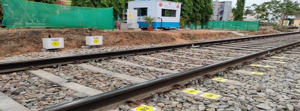
Wheel Impact Load Detector (WILD) is a system that quantifies the load imparted by the train on the rail(s) and measures the impact load of each wheel. As the wheel passes over the rail, the rail experiences di The instrumented FBG sensors measure this bending of the rail through variations in the reflected wavelength.


Fig.2: WILD system at LC15 Bangalore
The Bragg wavelength of FBG Sensors mainly depends on the applied strain to the grating and temperature surrounding it. FBG sensors on the track sense the dynamic impact load caused by the wheel-rail in contact. The FBG sensors will induce a shift in Bragg wavelength because of the impact of the force, and the measured wavelength shift can be used to compute the impact load. The packaged FBG strain sensor used in the system is capable of withstanding the impact load generated by the wheel rolling on the rail above it.
The FBG strain sensors are positioned below the rail, approximately midway between two sleepers as shown in Fig This position is chosen since the load imparted on the rail by the wheel of the train will result in the maximum bending moment and maximum deflection of the rail in between the sleepers.


Fig.3: Vertical load sensors on the rail
The sensors are packaged by embedding bare FBG sensors inside a stainless-steel housing and is terminated with armoured fibre optic cables on either end with suitable connectors. This design of packaged sensors can be used for measuring strain due to compression or tension. The packaged FBG sensors are fixed on two clamps for mounting on the rail.
The mounting process does not require any special preparation or any modification of the existing structure of the rail like drilling, glueing etc. The wavelength shift caused by the vertical forces exerted on the rail by a rolling wheel can be used to compute the impact load and to infer any wheel defect


Fig.4: FBG based Vibration sensor
A pair of FBG sensors are mounted on the web on either side of the rail, the lateral load produces strain due to tension on one sensor and strain due to compression on the other. The vertical load produces compression on both sensors. Therefore, by taking the difference between the two signals the vertical load components are cancelled and we get a resultant value that is proportional to the lateral load sensor sensing mechanism.

Fig.5: Lateral load sensor sensing mechanism